Homework 2 - CIS371 Spring 2012
| Instructor: | Prof. Milo Martin |
|---|---|
| Due: | Tuesday, February 28th at noon (turn in paper copy in class) |
| Alternative: | Use one "grace period" to turn it in on Tuesday, March 13th at noon. |
| Instructions: | Individual work. Show all your work to document how you came up with your answers. Please turn in a paper copy in class. We strongly encourage you to type up your answers. |
Cost and Yield. We talked about cost and yield issues only briefly in class, so this question will introduce you to the cost issues in manufacturing a design.
Your company's fabrication facility manufactures wafers at a cost of $5,000 per wafer. The wafers are 300mm in diameter (approximately 12 inches). This facility's average defect rate when producing these wafers is 1 defect per 400 mm2 (0.0025 defects per mm2). In this question, you will calculate the manufacturing cost per chip for 100 mm2, 200 mm2, and 400 mm2 chips.
The first step is to calculate the yield, the percentage of chips manufactured that are free of manufacturing defects using the following yield equation (from the appendix of the Patterson and Hennessy textbook):
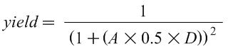
Where A is the area of the chip in mm2, D is the defects per mm2, and yield is a number between 0 and 1. Intuitively, this equation shows that if either the area of the chip or the defect rate increases, the yield decreases.
Based on this yield equation, what is this facility's yield for chips of 100 mm2, 200 mm2, 400 mm2?
Approximately how many good (defect-free) chips can be made from each wafer for each of these three chip sizes? (You can ignore the "square-peg-in-round-hole" effect.)
What is the manufacturing cost for each of these three chip sizes?
Leading Zero Count. One instruction included in many ISAs is a single-cycle "leading zero count" instruction that returns the number of leading zeros of a single input register. For example, the leading zero count of "00000000" would be 8; The leading zero count of "00111010" is two; the leading zero count of "10101000" is zero.
This circuit can be comprised of three parts. To make things concrete, we'll focus on a circuit with an 8-bit input and 4-bit output (more generally, n-bit input and log(n)+1-bit of output). The first step is to append a "one" to the number at the least significant bit to create a 9-bit value. The second step is to convert this value into a "one hot" encoding in which exactly one of the bits is set (and the rest are zeros). The bit that is a one is the first "one" bit of the input. For example, this circuit would convert "00111011" to "001000000" and "10101001" to "100000000". Third, an encoder converts the k-bit one-hot encoding to a log(k)-bit binary count (this is just a standard binary encoder circuit).
Design a "ripple-carry leading zero count" circuit by creating a single primitive (with two single-bit inputs and two single-bit outputs) that can be replicated n times to make an n-bit circuit to create the one-hot encoding (the second part from above).
Draw the gate-level diagram of the primitive building block described above.
Using a 9-to-4 encoder and multiple copies of the above building block, draw an 8-bit "leading zero counter".
Why do we need a 9-to-4 encoder and not just an 8-to-3 encoder? (Hint: it relates to why we shifted in the one to start with.)
What is the worst-case delay (in gate delays) of your 8-bit "leading zero counter"? Assume the 9-to-4 encoder has a delay of three.
Describe how the one of the techniques for fast arithmetic we discussed in class would directly apply to a leading zero count operation.
Carry-Select Adder Delay. In this question, you will calculate the delay of various carry-select adders. Use the same delay assumptions as was used in class: 2 units of delay for a mux, 2 units of delay for each bit of a ripple-carry adder. The individual segments are n-bit ripple-carry adders.
Using the above assumptions, what is the minimal size (in terms of number of bits) in which the carry-select adder is faster than a ripple-carry adder? Give the configuration and total delay of this adder.
What is the delay of a 64-bit carry-select adder with the optimal number of equal-sized segments?
Now consider a range of adder sizes: 8, 16, 24, 32, 40, 48, 56, and 64 bits. For each of these adders, calculate the delay with 1, 2, 4, and 8 equal-sized segments (a 1-segment carry-select adder is just a ripple-carry adder). The equation from the lecture notes will help you.
Plot the data as a line graph with the number of bits on the x-axis and the delay on the y-axis. The plot will have 4 lines, one for each number of segments. Be sure to label each axis.
Note: if the number of segments is larger than the number of bits, just don't plot that point on the graph.
Thus far we've only considered carry-select adders with equal-sized segments. However, using non-uniform length segments can results in a faster adder. Without the constraint of uniform segment lengths, how large of an adder (in terms of number of bits calculated) can be built with delay of 6? 8? 10? 12? 14?
Now consider non-uniform length segment carry-select adders for range of adder sizes: 8, 16, 24, 32, 40, 48, 56, and 64 bits. For each of these, calculate the delay of the fastest carry-select adder allowing non-uniform segments (Hint: build upon the answer from the previous question).
Plots this data by adding one line to the graph described above.
Performance I. Assume a typical program has the following instruction type breakdown:
- 30% loads
- 10% stores
- 50% adds
- 8% multiplies
- 2% divides
Assume the current-generation processor has the following instruction latencies:
- loads: 4 cycles
- stores: 4 cycles
- adds: 2 cycles
- multiplies: 16 cycles
- divides: 50 cycles
What is the CPI of this processor on this workload?
If for the next-generation design you could pick one type of instruction to make twice as fast (half the latency), which instruction type would you pick? Why? What is the new CPI after this change?
Averaging. Assume that a program executes one branch ever 4 instructions for the first 1M instructions and a branch every 8 instructions for the next 2M instructions. What is the average number instructions per branch for the entire program?
Performance II. Computer A executes the ARM ISA and has a 2.5Ghz clock frequency. Computer B executes the x86 and has a 3Ghz clock frequency. On average, programs execute 1.5 times as many ARM instructions than x86 instructions.
For Program P1, Computer A has a CPI of 2 and Computer B has a CPI of 3. Which computer is faster for P1? What is the speedup?
For Program P2, Computer A has a CPI of 1 and Computer B has a CPI of 2. Which computer is faster for P2? What is the speedup?
Assuming that Programs P1 and P2 are equally important workloads for the target market of this chip, which chip is "faster"? Calculate the average speedup.
Amdahl's Law. A program has 10% divide instructions. All non-divide instructions take one cycle. All divide instructions take 20 cycles.
What is the CPI of this program on this processor?
What percent of time is spent just doing divides?
What would the speedup be if we sped up divide by 2x?
What would the speedup be if we sped up divide by 5x?
What would the speedup be if we sped up divide by 20x?
What would the speedup be if divide instructions were infinitely fast (zero cycles)?
Pipelining. The standard pipeline discussed in class has five stages: fetch (F), decode (D), execute (X), memory (M), and writeback (W). The pipeline is fully bypassed and branches resolve at the end of the X stage. Consider the following six-stage pipelines, formed by spreading the logic of a single pipeline stage across two stages.
Increasing the pipelined depth generally hurts CPI. What specifically would cause the degradation in CPI of the pipeline if...
if the F stage was split into two stages (F1 and F2)?
if the D stage was split into two stages (D1 and D2)?
if the X stage was split into two stages (X1 and X2)? (Give three distinct impacts on CPI)
if the M stage was split into two stages (M1 and M2)?
Generally lengthening the pipeline improves the clock frequency. However, in some cases doing so could actually hurts the clock frequency. For example, how might splitting the M stage have a negative impact on the clock frequency? (Hint: we are not looking for a reason that splitting the stages will fail to improve the clock as much as expected. We're looking for a reason the clock frequency might actually get worse in an absolute sense.
Addendum
- None, yet.