{{FULL_COURSE}} Homework 3 - Rasterizer and Camera
Overview
-----
You will create a rasterizer for drawing scenes composed of 2D and 3D polygons.
To begin, you will develop a 2D triangle rasterization algorithm and test your
implementation on scenes composed of 2D polygons. Then, you will implement a
perspective projection camera in order to project 3D polygons down into 2D space
to be rasterized. You will code your own classes using C++ and will have your
first exposure to the Qt code libraries.
Supplied Code
---------
Click here to access
the homework's Github repository.
We will provide you with a basic Qt GUI that is capable of displaying QImages.
Make sure you read the code comments that explain how it works. Like the
previous assignment, you may make any changes you want to the code we give you.
Conceptual Questions (10 points, Due Friday, September 21 at 11:59 PM)
-------------
Before you begin the programming portion of this homework assignment, read and
answer the following conceptual questions. Your answers should be submitted as a
plaintext (`.txt`) file to the course dashboard.
* (2 pts) What are the three different configuration cases when determining the
intersection of a pixel row with a triangle edge? In all three cases, what
simple criterion can one use to determine whether the triangle edge overlaps
the pixel row at all?
* (3 pts) How might one use barycentric interpolation to determine whether or not a
given point in space lies within the bounds of a triangle? In rasterization,
would this method be more efficient than row bound checking for determining
which pixels lie within a triangle? Why or why not?
* (5 pts) Describe in detail the sequence of transformations that must occur in
order to project a set of triangles given in 3D world space into the coordinate
system of the pixelized screen.
Help Log (5 points)
-------
Maintain a log of all help you receive and resources you use. Make sure the date
and time, the names of everyone you work with or get help from, and every URL
you use, except as noted in the collaboration policy. Also briefly log your
question, bug or the topic you were looking up/discussing. Ideally, you should
also the answer to your question or solution to your bug. This will help you
learn and provide a useful reference for future assignments and exams. This also
helps us know if there is a topic that people are finding difficult.
If you did not use external resources or otherwise receive help, please submit
a help log that states you did not receive external help.
You may submit your help log as an ASCII (plain) text file or as a PDF. Refer
to the Policies section of the course web site for more specifications.
2D Triangle Rasterization Features (40 points, Due Wednesday, September 26 at 11:59 PM)
-------
Classes you will edit:
* Rasterizer
* Polygon
Classes you won't need to edit (but may edit if you so choose)
* Triangle
* Vertex
* MainWindow
* tinyobj
The `Rasterizer` class contains a function named `RenderScene()` that returns a
512x512 `QImage` to be displayed in the GUI. The `QImage` should be constructed
to use the `RGB_32` format. You will have to implement several functions and
classes to properly output a rasterized image. It is important to note that the
features listed below do not necessarily have to be completed in the order they
are written. When you initialize your `QImage`, make sure to populate its pixels
with black using the `fill` function. When you use `QColor`s elsewhere in your
code, you should assign them values using the `qRgb` function, e.g.
`QColor c = qRgb(255, 0, 0);`. Note that `QColors` expect values in the range
[0, 255] rather than [0, 1].
For reference images of expected results, refer to the bottom of this page.
### Convex polygon triangulation (5 points) ###
We have provided you with a `Polygon` class and a function in `MainWindow` that
creates and stores polygons based on an input JSON file. You will have to write
code for the `Polygon` class's `Triangulate()` function that populates the
`Polygon`'s list of `Triangle`s. You may assume that the vertices listed for
`Polygon`s in the input JSON files are always in counter-clockwise order, and
that they always define a convex polygon.
If you wish to test your rendering functionality on triangles without
implementing triangulation, we have provided you with a function that
automatically creates an equilateral triangle Polygon and sets it in the
scene's list of `Polygon`s. You can access this from the Scenes dropdown menu
in the GUI.
### Line segments (5 points) ###
Create a class that represents a 2D line segment, to be used when determining
which pixels on a row a triangle overlaps. It should contain the following
member variables:
* Two vectors representing the segment's endpoints. __These vectors should
store their data as floating point numbers, as it is very rare that points
projected into screen space in the projection portion of this assignment
will align exactly with a pixel.__
* A variable (or variables) for storing the slope of the line segment. This will
help you to determine which of the three configuration cases the segment falls
into without having to compute the slope more than once. Remember that your
slope should be stored as a float (or floats if you're storing dX and dY).
Your line segment class should also implement the following functions:
* A constructor that takes in both endpoints of the line segment. The
constructor should make use of an initialization list to assign values to __all__
member variables.
* A function that computes the x-intersection of the line segment with a
horizontal line based on the horizontal line's y-coordinate. This function
should return a boolean indicating whether or not the lines intersect at all,
while using a pointer as a function input to write the x-intersection. For
example, `bool getIntersection(int y, float* x) {...}`
### Bounding boxes (5 points) ###
Create a way to compute and store the 2D axis-aligned bounding box of a
triangle. You will use these bounding boxes to improve the efficiency of
rendering each triangle. Rather than testing every single row of the screen
against a triangle, you will only test the screen rows contained within the
triangle's bounding box. Remember to clamp each bounding box to the screen's
limits.
### Triangle rendering (10 points) ###
The `Rasterizer` class contains a function called `RenderScene()`. Using the
code you wrote for the features listed above, you should be able to draw
triangles on the QImage set up in this function using pixel row overlap testing.
At this point, you may draw the triangles using a single color for testing.
However, once you complete the next requirement you will be able to draw your
shapes properly with interpolated vertex colors.
### Barycentric interpolation (10 points) ###
Implement a function that, for a given `Triangle` and point within the `Triangle`,
returns the barycentric influence that each vertex exerts on any attribute
interpolated at the input point. Note that the return value is really three
distinct values, so returning them as a vector is the most straightforward
method.
You will use this interpolation function to properly color the pixels that lie
within a triangle. Each pixel should have a blended color based on the color of
each vertex of the triangle. The weighting of the blending will be determined by
this barycentric interpolation function.
### Z-buffering (5 points) ###
Rather than using the Painter's Algorithm as you did in the previous assignment,
you should sort the Z coordinates of your triangles on a per-fragment basis
rather than a per-triangle basis. We recommend that you create an array of
floating point numbers in which to store the depth of the fragment that is
currently being used to color a given pixel. Note that it is more efficient to
store this data in a one-dimensional array rather than a two-dimensional array.
If your image is W x H pixels, then your array should contain W \* H elements,
and you can access the element corresponding to `(x, y)` as `array[x + W * y]`.
This type of indexing can be extended to N dimensions, e.g.
`x + W * y + W * H * z` for three dimensions.
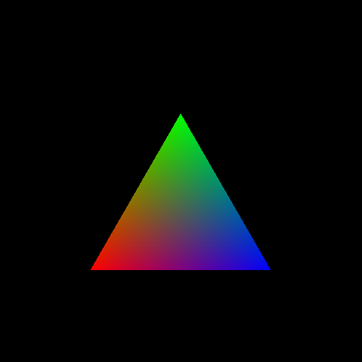
### Testing your implementation so far ###
Once you've implemented all of the features of the 2D triangle rasterizer, you
should be able to render all of the JSON scenes with the `2D_` prefix. Here
are reference images to which you can compare your results:
equilateral_triangle.json
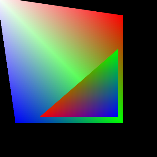
two_polygons.json
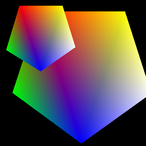
regular_pentagon.json
pentagons.json
3D Triangle Rasterization Requirements (50 points, Due Wednesday, September 26 at 11:59 PM)
---------------
Once you've made sure you've successfully implemented all of the 2D
rasterization requirements, you may move on to implementing the 3D rasterization
features. Once you've implemented them all, you can test your rasterizer on the
JSON scenes with the `3D_` prefix. Note that after you've implemented the 3D
features, the 2D rasterizer scenes will not render correctly anymore, which is
expected.
### Perspective Camera class (15 points) ###
Create a Camera class that you will use to generate view matrices and
perspective projection matrices. Your camera should contain the following member
variables which will be assigned the following values by the camera's default
constructor:
* A vector that represents the camera's "forward" direction, i.e. its Z axis.
Default value of <0, 0, -1, 0>.
* A vector that represents the camera's "right" direction, i.e. its X axis.
Default value of <1, 0, 0, 0>.
* A vector that represents the camera's "up" direction, i.e. its Y axis.
Default value of <0, 1, 0, 0>.
* A value for the camera's vertical field of view. Default value of 45 degrees.
* A vector that represents the camera's position in world space.
Default value of <0, 0, 10, 1>.
* A floating point number representing the camera's near clip plane.
Default value of 0.01.
* A floating point number representing the camera's far clip plane.
Default value of 100.0.
* A floating point number representing the camera's aspect ratio.
Default value of 1.0.
Additionally, your camera should implement the following functions:
* A function which returns a view matrix based on the camera's local axes
and position. You may __not__ use GLM's `lookAt` function for this.
* A function which returns a perspective projection matrix based on
the camera's clipping planes, aspect ratio, and field of view. You may __not__
use GLM's `persp` function for this.
* Three functions that translate the camera along each of its local axes,
both forward and backward. The amount of translation should be determined by
an input to the function.
* Three functions that rotate the camera about each of its local axes. Note that
these functions should only alter the orientation of the camera; its position
should not change. The amount of rotation should be determined by an input to
the function.
### Interactive camera (5 points) ###
In `MainWindow`'s `keyPressEvent` function, add switch cases that call the
movement functions you implemented for the `Camera` class. For example, when the
user presses the W key, the camera could move along its local Z axis. The
particulars of your control scheme are up to you, but please document them in
your `readme` file, as described in the Submission section of this page.
Note that your rasterizer may take a few moments to display
the scene from the camera's new vantage point, especially if you are rendering
a polygon mesh with many faces.
This `keyPressEvent` function will be called by Qt's `QMainWindow` class (from
which our `MainWindow` inherits) whenever the user presses a key on his or her
keyboard. If some of your keypresses seem to not be working, try clicking on
the grey background of the main window (i.e. NOT the rendered image) to give
your main window keyboard focus.
### Texture mapping (10 points) ###
Each of the 3D JSON files provided with this assignment specify an image file to be
loaded as the texture for the OBJ file noted in the JSON. Using the UV
coordinates stored in each Vertex of the polygon mesh loaded from the OBJ file,
map the texture colors to the surface of the polygon mesh using barycentric
interpolation. Note that none of the objects contained in the 3D JSON files have
colors assigned to each vertex as they did in the 2D scenes.
If you wish to test and implement other features before this step, we recommend
that you assign a default surface color to geometry to use in place of its
texture colors, such as grey or bubblegum pink.
### Perspective-correct interpolation (15 points) ###
In order to correctly compute the Z coordinate and UV coordinates of your pixel
fragments, you must implement two modified methods of barycentric interpolation.
Based on the methods described in the lecture slides, interpolate each
fragment's Z with correct perspective distortion, then interpolate each
fragment's UVs with correct perspective distortion. Recall that once you have
a perspective-correct Z coordinate for a fragment, you can properly interpolate
any other per-vertex data, such as surface normal or color. In order for your
renderings to match the reference images below, you will need to interpolate
the triangle vertices' surface normals as well.
### Lambertian reflection (5 points) ###
Using the camera's look vector as the light direction in your scene, use the
Lambertian reflection model to attenuate the brightness of each point on the
surface of a mesh. We also recommend you add some amount of ambient light to
your reflection formula so that faces that are "completely dark" are still
slightly lit and therefore visible.
### 3D Rasterizer Reference Images ###
Refer to these images to make sure you've correctly implemented the features
listed above:
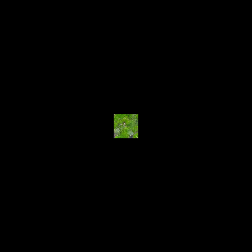
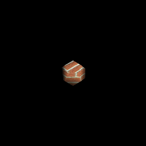
cube.json
dodecahedron.json
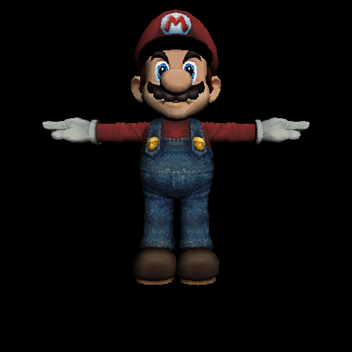
wahoo.json (no Lambertian shading)
wahoo.json (with Lambertian shading)
Coding Style (10 points)
-------
We will provide you with feedback on the organization and clarity of the code
you have written for this assignment. Please refer to our course style guide as
you implement your rasterizer.
Extra Credit (Maximum 30 points)
---------
Include a readme.txt file in your repository that lists which extra credit
features you implemented and how to display them.
### Custom JSONs with OBJs (5 pts) ###
Compose an interesting scene with OBJ files. To earn points for this, it is not
enough to just plop a single OBJ in a JSON and render it, unless that OBJ is
really several models in one scene. Basically, we want you to put together a
scene that might look nice on a demo reel.
### Anti-aliasing (10 - 20 points) ###
You've probably noticed that the diagonal edges of your polygons are jagged in
appearance. This is due to aliasing, which is the lack of sufficient sampling of
a signal (in this case, the "signal" is the polygon being rendered). A simple
way to counteract this aliasing is to sample the image more frequently. In a
rasterizer, this effectively means rendering the image at a higher resolution
and then scaling the image down, treating every block of NxN pixels as a single
pixel in the final image. When downscaling the image, one averages the colors
of each NxN block into a single color. For example, the image below has been
rendered at 4x its actual resolution then scaled down to a 512x512 image.
Remember that the scene files we provide assume the images you render will be
512x512 in size. If you render an image at 1024x1024 to anti-alias it, you will
have to treat each pixel as a 0.5x0.5 square or every polygon as being 2x its
actual size. To earn 10 points, perform anti-aliasing by just rendering your
scene at one higher resolution then scaling it down. To earn 20 points, add
options to your Qt GUI that allow the user to perform anti-aliasing at different
levels of scaling, such as 1x, 4x, 9x, or 16x. If you implement this option,
your code should not have if-else statements to handle the anti-aliasing.
No AA
4x AA
### Line rendering (15 points) ###
Add an option to your GUI (e.g. a dropdown menu choice) that allows the user to
render all the triangles in your scene as wireframes rather than solid faces.
This means only coloring pixels that each edge of the triangle overlaps, and
using linear interpolation to color each pixel on the line. If you're interested
in efficient rendering of lines, you might look into Bresenham's line algorithm.
### Concave polygon triangulation (25 points) ###
Given a custom polygon JSON scene, determine whether or not each polygon is
concave. If a polygon is concave, divide it up into convex subcomponents then
triangulate them. You may use whatever method of division you wish.
### Normal mapping (10 points) ###
Using the normal map images provided with this assignment, implement normal
displacement on a per-fragment level. Of the provided JSON files, only
`dodecahedron.json` has a normal map applied. You are free to create additional
JSONs with other normal maps applied to objects.
Implementing normal mapping does mean that you will have to implement UV-based
tangent and bitangent vectors. When implementing this, it is simpler to use
the geometric normal of your triangle rather than the per-vertex normals.
Recall that you can compute the geometric normal of any triangle by taking the
normalized cross product of any two of its edges.
### Additional reflection models (5 + varying points) ###
Implement at least one of the reflection models we discussed in lecture
previously:
* Blinn-Phong (7 pts)
* Iridescent (5 pts)
* Lit sphere (8 pts)
* Toon (5 pts)
* Custom (?? pts)
Add a drop-down menu to your GUI to allow the user to switch between different
models. Post a private question on Piazza if you wish to implement a custom
reflection model.
### Parallel processing (30 points) ###
Using the `QThreadPool` and `QRunnable` classes, enable your program to process
multiple pixel rows at once per triangle. This will require you to make a class
that inherits from `QRunnable`, perhaps a class that represents a pixel row, and
implement `QRunnable::run()` to allow the `QThreadPool` to handle the render
task.
[Here is the documentation for the QThreadPool class.](https://doc.qt.io/qt-5/qthreadpool.html#details0)
Submission
--------
We will grade the code you have pushed to your GitHub repository, so make sure
that you have correctly committed all of your files! Once you have pushed your
finished project to GitHub, submit a link to your commit through the course
dashboard. If you click on the Commits tab of your repository on Github, you
will be brought to a list of commits you've made. Simply click on the one you
wish for us to grade, then copy and paste the URL of the page into your text
file.