Overview
-----
You will create a rasterizer for drawing scenes composed of 2D polygons. This
rasterizer will be extended upon in the next homework assignment wherein you
will write a camera class to project 3D polygons into 2D space and rasterize
them. You will code your own classes using C++ and will have your first exposure
to the Qt code libraries.
Supplied Code
---------
Click here to access the homework's Github repository.
We will provide you with a basic Qt GUI that is capable of displaying QImages.
Make sure you read the code comments that explain how it works. Unlike the
previous assignment, you may make any changes you want to the code we give you.
Please note that the coordinate system of the images has X increasing from left
to right and Y increasing from top to bottom.
Additionally, we have provided a robust library of linear algebra functions
called GLM (OpenGL Mathematics) to use for your transformation needs. The
library you wrote for homework 1 was designed to be very similar in format to
the classes and functions provided by GLM, but there are some differences in
inputs to the transformation matrix functions GLM provides.
You can find the
(admittedly difficult to navigate) documentation for GLM here.
Conceptual Questions (10 points, Due Friday, September 15 at 11:59 PM)
-------------
Before you begin the programming portion of this homework assignment, read and
answer the following conceptual questions. Your answers should be submitted as a
plaintext (`.txt`) file to the dashboard.
* (5 pts) What are the three different configuration cases when determining the
intersection of a pixel row with a triangle edge? In all three cases, what
simple criterion can one use to determine whether the triangle edge overlaps
the pixel row at all?
* (5 pts) How might one use barycentric interpolation to determine whether or not a
given point in space lies within the bounds of a triangle? In rasterization,
would this method be more efficient than row bound checking for determining
which pixels lie within a triangle? Why or why not?
Help Log (5 points)
-------
Maintain a log of all help you receive and resources you use. Make sure the date
and time, the names of everyone you work with or get help from, and every URL
you use, except as noted in the collaboration policy. Also briefly log your
question, bug or the topic you were looking up/discussing. Ideally, you should
also the answer to your question or solution to your bug. This will help you
learn and provide a useful reference for future assignments and exams. This also
helps us know if there is a topic that people are finding difficult.
You may submit your help log as an ASCII (plain) text file or as a PDF. Refer to the Policies section of the course web site for more specifications.
Code Requirements (85 points, Due Wednesday, September 20 at 11:19 PM)
-------
Classes you will edit:
* Rasterizer
* Polygon
Classes you won't need to edit (but may edit if you so choose)
* Triangle
* Vertex
* MainWindow
* tinyobj
The `Rasterizer` class contains a function named `RenderScene()` that returns a
512x512 `QImage` to be displayed in the GUI. The `QImage` should use the `RGB_32` format.
You will have to implement several functions and classes to properly output a
rasterized image. It is important to note that the features listed below do
not necessarily have to be completed in the order they are written. When you
initialize your `QImage`, make sure to populate its pixels with black.
For reference images of expected results, refer to the bottom of this page.
### Convex polygon triangulation (15 points) ###
We have provided you with a `Polygon` class and a function in `MainWindow` that
creates and stores polygons based on an input JSON file. You will have to write
code for the `Polygon` class's `Triangulate()` function that populates the
`Polygon`'s list of `Triangle`s. You may assume that the vertices listed for
`Polygon`s in the input JSON files are always in counter-clockwise order, and
that they always define a convex polygon.
If you wish to test your rendering functionality on triangles without
implementing triangulation, we have provided you with a function that
automatically creates an equilateral triangle Polygon and sets it in the
scene's list of `Polygon`s. You can access this from the Scenes dropdown menu
in the GUI.
### Line segments (20 points) ###
Create a class that represents a 2D line segment, to be used when determining
which pixels on a row a triangle overlaps. You may choose to make it in a new
header file, or add it to an existing one. It should contain the following
member variables:
* Two vectors representing the segment's endpoints. We recommend making these
vectors at least three-dimensional, since the Z coordinate of the lines will
be important.
* A variable (or variables) for storing the slope of the line segment. This will
help you to determine which of the three configuration cases the segment falls
into without having to compute the slope more than once.
Your line segment class should also implement the following functions:
* A constructor that takes in both endpoints of the line segment. The
constructor should make use of an initialization list to assign values to __all__
member variables.
* A function that computes the x-intersection of the line segment with a
horizontal line based on the horizontal line's y-coordinate. This function
should return a boolean indicating whether or not the lines intersect at all,
while using a pointer as a function input to write the x-intersection.
### Bounding boxes (10 points) ###
Create a way to compute and store the 2D axis-aligned bounding box of a
triangle. You will use these bounding boxes to improve the efficiency of
rendering each triangle. Rather than testing every single row of the screen
against a triangle, you will only test the screen rows contained within the
triangle's bounding box.
### Triangle rendering (15 points) ###
The `Rasterizer` class contains a function called `RenderScene()`. Using the
code you wrote for the features listed above, you should be able to draw
triangles on the QImage set up in this function using pixel row overlap testing.
At this point, you may draw the triangles using a single color for testing.
However, once you complete the next requirement you will be able to draw your
shapes properly with interpolated vertex colors.
### Barycentric interpolation (15 points) ###
Implement a function that, for a given `Triangle` and point within the `Triangle`,
returns the barycentric influence that each vertex exerts on any attribute
interpolated at the input point. Note that the return value is really three
distinct values, so returning them as a vector is the most straightforward
method.
You will use this interpolation function to properly color the pixels that lie
within a triangle. Each pixel should have a blended color based on the color of
each vertex of the triangle. The weighting of the blending will be determined by
this barycentric interpolation function.
### Painter's algorithm (10 points) ###
In the scenes we provide you, each polygon has the same Z coordinate for each of
its vertices. Given this feature, use the Painter's Algorithm to sort each
polygon by depth, back to front, then draw the polygons in sorted order.
In computer graphics, we treat lower depth values as being closer to the camera,
so you should sort your polygons from high to low. We recommend you use
`std::sort` to perform this operation, which means you'd have to implement
a comparator function for the `Polygon` or `Triangle` class. A comparator
function takes in two `const` references to the objects it is supposed to
compare and returns a boolean that states whether or not the first of the
two inputs is "less than" the second. Determining the meaning of "less
than" depends on the objects being compared; in the case of two `Polygons`, one
`Polygon` is "less than" another if its Z coordinate is smaller.
Coding Style (10 points)
-------
We will provide you with feedback on the organization and clarity of the code
you have written for this assignment. Please refer to our course style guide as
you implement your rasterizer. When coding this assignment, consider places you
might bundle code into helper functions to improve the human readability of your
program. Also remember: when you find yourself copying and pasting your own code,
think about how you could reduce that code with a loop or helper function.
Extra Credit (Maximum 30 points)
---------
If you implement any extra credit, please document it your `readme.txt`, as
described in the Submission section at the bottom of this page.
### Custom scene (5 points) ###
Write a JSON scene file that, when rendered, displays an interesting scene.
For example, you could create an environment with characters interacting.
### Anti-aliasing (10 - 20 points) ###
You've probably noticed that the diagonal edges of your polygons are jagged in
appearance. This is due to aliasing, which is the lack of sufficient sampling of
a signal (in this case, the "signal" is the polygon being rendered). A simple
way to counteract this aliasing is to sample the image more frequently. In a
rasterizer, this effectively means rendering the image at a higher resolution
and then scaling the image down, treating every block of NxN pixels as a single
pixel in the final image. When downscaling the image, one averages the colors
of each NxN block into a single color. For example, the image below has been
rendered at 4x its actual resolution then scaled down to a 512x512 image.
Remember that the scene files we provide assume the images you render will be
512x512 in size. If you render an image at 1024x1024 to anti-alias it, you will
have to treat each pixel as a 0.5x0.5 square or every polygon as being 2x its
actual size. To earn 10 points, perform anti-aliasing by just rendering your
scene at one higher resolution then scaling it down. To earn 20 points, add
options to your Qt GUI that allow the user to perform anti-aliasing at different
levels of scaling, such as 1x, 4x, 9x, or 16x. If you implement this option,
your code should not have if-else statements to handle the anti-aliasing.
No AA
4x AA
### Line rendering (15 points) ###
Add an option to your GUI (e.g. a dropdown menu choice) that allows the user to
render all the triangles in your scene as wireframes rather than solid faces.
This means only coloring pixels that each edge of the triangle overlaps, and
using linear interpolation to color each pixel on the line. If you're interested
in efficient rendering of lines, you might look into Bresenham's line algorithm.
### Concave polygon triangulation (25 points) ###
Given a custom polygon JSON scene, determine whether or not each polygon is
concave. If a polygon is concave, divide it up into convex subcomponents then
triangulate them. You may use whatever method of division you wish.
Reference images
-------
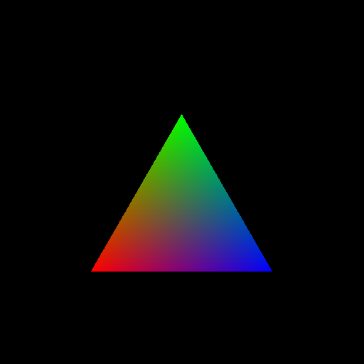
Below are the expected results of rendering certain scenes. Use these to make
sure you've properly implemented your functions.
If you have some space between the triangles that compose your polygons, try
rounding your left intersections down to the nearest pixel and your right
intersections up to the nearest pixel.
equilateral_triangle.json
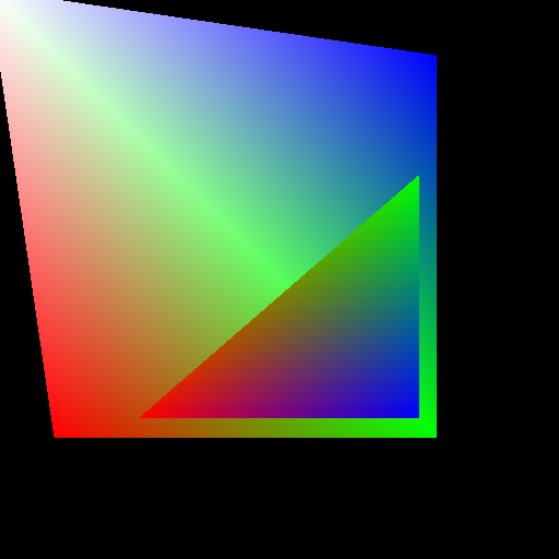
two_polygons.json
regular_pentagon.json
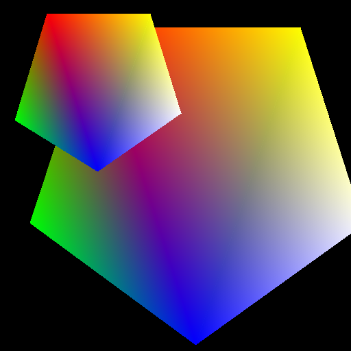
pentagons.json
Submission
--------
Make sure your homework compiles in the Moore labs. We will deduct points from
any homework that does not compile, and possibly give a 0 grade if the compile
errors are numerous. __Along with your code, make sure to include a `readme.txt`
file at the topmost level of your repository that includes any notes on your
implementation you'd like us to know, along with any extra credit you've
implemented.__ We will grade the code you have pushed to your GitHub
repository, so make sure that you have correctly committed all of your files!
Once you have pushed your finished project to GitHub, submit a link to your
commit through the course dashboard. If you click on the Commits tab of your
repository on Github, you will be brought to a list of commits you've made.
Simply click on the one you wish for us to grade, then copy and paste the URL
of the page into your text file.