Homework 1 - CIS371 Spring 2011
| Instructor: | Prof. Milo Martin |
|---|---|
| Due: | Friday, Feb 25th at 6pm (turn in a PDF file via BlackBoard) |
| Instructions: | Show all your work to document how you came up with your answers. To turn in your assignment, submit a PDF file to blackboard. Do not submit Word documents; please print/convert them to PDF first. |
Cost and Yield. We talked about cost and yield issues only briefly in class, so this question will introduce you to the cost issues in manufacturing a design.
Your company's fabrication facility manufactures wafers at a cost of $50,000 per wafer. The wafers are 300mm in diameter (approximately 12 inches). This facility's average defect rate when producing these wafers is 1 defect per 400 mm2 (0.0025 defects per mm2). In this question, you will calculate the manufacturing cost per chip for 100 mm2, 200 mm2, and 400 mm2 chips.
The first step is to calculate the yield, the percentage of chips manufactured that are free of manufacturing defects using the following yield equation (from the appendix of the Patterson and Hennessy textbook):
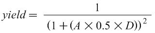
Where A is the area of the chip in mm2, D is the defects per mm2, and yield is a number between 0 and 1. Intuitively, this equation shows that if either the area of the chip or the defect rate increases, the yield decreases.
Based on this yield equation, what is this facility's yield for chips of 100 mm2, 200 mm2, 400 mm2?
Approximately how many good (defect-free) chips can be made from each wafer for each of these three chip sizes? (You can ignore the "square-peg-in-round-hole" effect.)
What is the manufacturing cost for each of these three chip sizes?
Leading Zero Count. One instruction included in many ISAs is a single-cycle "leading zero count" instruction that returns the number of leading zeros of a single input register. For example, the leading zero count of "00000000" would be 8; The leading zero count of "00111010" is two; the leading zero count of "10101000" is zero.
This circuit can be comprised of three parts. To make things concrete, we'll focus on a circuit with an 8-bit input and 4-bit output (more generally, n-bit input and log(n)+1-bit of output). The first step is to append a "one" to the number at the least significant bit to create a 9-bit value. The second step is to convert this value into a "one hot" encoding in which exactly one of the bits is set (and the rest are zeros). The bit that is a one is the first "one" bit of the input. For example, this circuit would convert "00111011" to "001000000" and "10101001" to "100000000". Third, an encoder converts the k-bit one-hot encoding to a log(k)-bit binary count (this is just a standard binary encoder circuit).
Design a "ripple-carry leading zero count" circuit by creating a single primitive (with two single-bit inputs and two single-bit outputs) that can be replicated n times to make an n-bit circuit to create the one-hot encoding (the second part from above).
Draw the gate-level diagram of the primitive building block described above.
Using a 9-to-4 encoder and multiple copies of the above building block, draw an 8-bit "leading zero counter".
Why do we need a 9-to-4 encoder and not just an 8-to-3 encoder? (Hint: it relates to why we shifted in the one to start with.)
What is the worst-case delay (in gate delays) of your 8-bit "leading zero counter"? Assume the 9-to-4 encoder has a delay of three.
Describe how the one of the techniques for fast arithmetic we discussed in class would directly apply to a leading zero count operation.
How would this circuit change if you wanted to count trailing zeros (rather than leading zeros)?
How would this circuit change if you wanted to count leading ones (rather than zeros)?
Carry-Select Adder Delay. In this question, you will calculate the delay of various carry-select adders. Use the same delay assumptions as was used in class: 2 units of delay for a mux, 2 units of delay for each bit of a ripple-carry adder. The individual segments are n-bit ripple-carry adders.
Using the above assumptions, what is the minimal size (in terms of number of bits) in which the carry-select adder is faster than a ripple-carry adder? Give the configuration and total delay of this adder.
What is the delay of a 64-bit carry-select adder with the optimal number of equal-sized segments?
Now consider a range of adder sizes: 8, 16, 24, 32, 40, 48, 56, and 64 bits. For each of these adders, calculate the delay with 1, 2, 4, 8, and 16 equal-sized segments (a 1-segment carry-select adder is just a ripple-carry adder). The equation from the lecture notes will help you.
Plot the data as a line graph with the number of bits on the x-axis and the delay on the y-axis. The plot will have 5 lines, one for each number of segments. Be sure to label each axis.
Note: if the number of segments is larger than the number of bits, just don't plot that point on the graph.
Thus far we've only considered carry-select adders with equal-sized segments. However, using non-uniform length segments can results in a faster adder. Without the constraint of uniform segment lengths, how large of an adder (in terms of number of bits calculated) can be built with delay of 6? 8? 10? 12? 14?
Now consider non-uniform length segment carry-select adders for range of adder sizes: 8, 16, 24, 32, 40, 48, 56, and 64 bits. For each of these, calculate the delay of the fastest carry-select adder allowing non-uniform segments (Hint: build upon the answer from the previous question).
Plots this data by adding one line to the graph described above.
What is the delay of a 64-bit carry-select adder with the fastest non-uniform length segments? For this delay, give the configuration with the fewest number of segments. Include the bit width of each of the segments in your answer.
Performance I. Computer A executes the ARM ISA and has a 2.5Ghz clock frequency. Computer B executes the x86 and has a 3Ghz clock frequency. On average, programs execute 1.5 times as many ARM instructions than x86 instructions.
- For Program P1, Computer A has a CPI of 2 and Computer B has a CPI of 3. Which computer is faster for P1? What is the speedup?
- For Program P2, Computer A has a CPI of 1 and Computer B has a CPI of 2. Which computer is faster for P2? What is the speedup?
Performance II. Assume a typical program has the following instruction type breakdown:
- 30% loads
- 10% stores
- 50% adds
- 8% multiplies
- 2% divides
Assume the current-generation processor has the following instruction latencies:
- loads: 4 cycles
- stores: 4 cycles
- adds: 2 cycles
- multiplies: 16 cycles
- divides: 50 cycles
What is the CPI of this processor on this workload?
If for the next-generation design you could pick one type of instruction to make twice as fast (half the latency), which instruction type would you pick? Why? What is the new CPI after this change?
Averaging. Assume that a program executes one branch ever 4 instructions for the first 1M instructions and a branch every 8 instructions for the next 2M instructions. What is the average number instructions per branch for the entire program?
Amdahl's Law. A program has 10% divide instructions. All non-divide instructions take one cycle. All divide instructions take 20 cycles.
- What is the CPI of this program on this processor?
- What percent of time is spent just doing divides?
- What would the speedup be if we sped up divide by 2x?
- What would the speedup be if we sped up divide by 5x?
- What would the speedup be if we sped up divide by 20x?
- What would the speedup be if divide instructions were infinitely fast (zero cycles)?
Effectiveness of Compiler Optimizations. The compiler's goal is to generate the fastest code for the given input program. The programmer specifies the "optimization" level the compiler performs. To ask the compiler to perform no compiler optimizations, the "-O0" flag can be used (that is "dash oh zero"). This is useful when debugging. It is also the fastest compilation and the least likely to encounter bugs in the compiler. The flag "-O2" (dash oh two) flag enables optimizations, the "-O3" (dash oh three) enables even more optimizations. Finally, the flag "-funroll-loops" enables yet another compiler optimization.
This question asks you to explore the impact of compiler optimizations using the following simple single-precision "a*x+y" (saxpy) vector-vector operation:
#define ARRAY_SIZE 1024

float x[ARRAY_SIZE];
float y[ARRAY_SIZE];
float z[ARRAY_SIZE];
float a;

void saxpy()
{
  for(int i = 0; i < ARRAY_SIZE; i++) {
    z[i] = a*x[i] + y[i];
  }
}
See code.c for this code with all the proper defines. Log into minus.seas.upenn.edu via SSH, and compile the code with three different levels of optimization:
gcc -O0 -Wall -std=c99 -S code.c -o code-O0.s
gcc -O2 -Wall -std=c99 -S code.c -o code-O2.s
gcc -O3 -fno-tree-vectorize -Wall -std=c99 -S code.c -o code-O3.s
gcc -O3 -funroll-loops -fno-tree-vectorize -Wall -std=c99 -S code.c -o code-O3-unrolled.s
gcc -O3 -funroll-loops -ftree-vectorize -Wall -std=c99 -S code.c -o code-O3-unrolled-vector.s
This will create four .s files in the directory (code-O0.s, code-O2.s, code-O3.s, code-O3-unrolled.s, code-O3-unrolled-vector.s). These files are the x86 assembly of this function. You can ignore everything except the code between the label saxpy and the return statement (ret).
Note
You don't have to understand much x86 code to answer the following questions, but you may find seeing actual x86 code interesting. For example, instead of using "load" and "store" instructions, in x86 these instructions are both "mov" (move) instructions. An instruction like add %ecx, (%esp) performs both a memory access and an add (an example of a CISC-y x86 instruction). The x86 ISA also has some more advanced memory addressing modes, such Also, x86 uses condition codes, so jump (branch) instructions don't have explicit register inputs. If you want to lookup an x86 instruction, you may find the Intel x86 reference manual useful: http://www.intel.com/products/processor/manuals/
Note
The flag -ftree-vectorize enables "automatic vectorization". This computation is one that GCC can vectorize, so GCC uses "packed" versions of the various instructions that operate on four elements of the array at a time (that is, load four values, multiple four value, store four values, etc.).
For each of these files, answer the following questions:
- What is the static instruction count (the number of instructions in the source code listing) of the loop (just ignore the header and footer code to count the number of instructions in the loop)?
Based on the number of instructions in the loop (above) and the number of iterations of the loop in each .s file, calculate the approximate number of dynamic instructions executed by the loop in the function (approximately, to the nearest few hundred instructions).
Assuming a processor with a CPI of 1, how much "faster than" is the -O2 than -O0? How much faster is -O3 than -O2? How much is unrolled faster than -O3? How much is vectorized over -O3 + unrolling?
- When comparing the last two optimized .s files, how does the number of static instructions relate to the dynamic instruction count? Give a brief explanation.
- Using what you learned from this data, what is one advantage and one disadvantage of loop unrolling?
Next, run the four versions. To do this, link each source file with driver.c and run it. The driver calls the function 1 million (1,000,000) times and reports the runtime in seconds:
gcc -static code-O0.s driver.c -o code-O0
gcc -static code-O2.s driver.c -o code-O2
gcc -static code-O3.s driver.c -o code-O3
gcc -static code-O3-unrolled.s driver.c -o code-O3-unrolled
gcc -static code-O3-unrolled-vector.s driver.c -o code-O3-unrolled-vector

./code-O0
./code-O2
./code-O3
./code-O3-unrolled
./code-O3-unrolled-vector
Give the runtime of each of these versions. How much faster is -O2 that -O0? How much faster is -O2 over -O3? How much faster is unrolled over -O3? How much faster is unrolled & vectorized over just unrolled? How does this compare to your estimate above based only on instruction counts?
The clock frequency of the processors in "minus.seas.upenn.edu" is 3.0 Ghz (3 billion cycles per second). Based on your estimate of the number of instructions in each call to the function and that driver.c calls the function 1 million times, calculate the CPI of the processor running each of these programs.
What do the above CPI numbers tell you about these compiler optimizations? You may wish to calculate the IPC of each, as sometimes it is easier to reason about IPC (instructions per cycle) rather than CPI (the inverse metric).
Addendum
- [Feb 24] Clarified to also give the speedup of vectorization in part (c) of the last question.
- [Feb 17] Fixed the -fno-tree-vectorize command line option